CPFE simulation preprocessing GUIs
The preCPFE GUIs can rapidly transfer the experimental data into crystal plasticity finite element (CPFE) simulation input files. The types of input files are:
scripts to generate the finite element models in MSC.Mentat (2008 to 2014) (procedure file format) or Abaqus (6.12 to 6.14) (Python script) based on the experimental data and test geometry;
the crystallographic orientations from the experimental data sets;
material parameter files for the subroutines that implement the constitutive model.
A parametrized visualization of the bicrystal indentation model through the GUI allows tuning the geometry and finite element discretization and the size of the sample and the indenter.
Currently the following models can be written:
Single crystal (SX) indentation (MSC.Mentat and Abaqus)
Bicrystal (BX) indentation (MSC.Mentat and Abaqus)
Scratch test on SX and BX (MSC.Mentat and Abaqus)
Please find here the Python package used to generate the SX and BX indentation models.
Note
From 2022, DAMASK is not working anymore with Abaqus, check here for more information: https://damask.mpie.de/index.html
How to load crystallographic properties of the SX or of the BX?
It is possible to set SX or BX properties (material, phase, Euler angles, trace angle…):
from the Bicrystal GUI (by giving GB’s number and pressing the button ‘PLOT BICRYSTAL’);
from a YAML configuration file (from the menu, by clicking on ‘preCPFE-SX’ or ‘preCPFE-BX’, and ‘Load Single Crystal config. file’ or ‘Load Bicrystal config. file’).
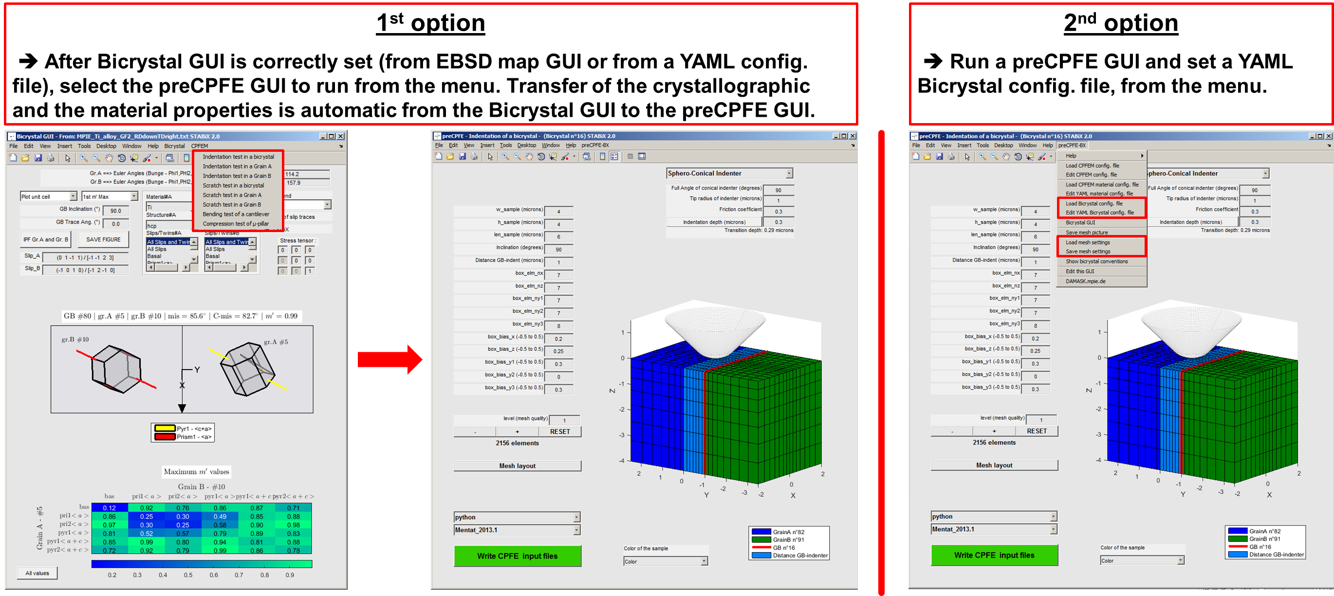
Figure 26 The different steps to set the preCPFE GUIs.
Single crystal (SX) indentation
Analysis of the orientation dependent pile-up topographies that are formed during single crystal indentation provides insight into the operating deformation mechanisms. CPFE simulation of single crystal indentation has an important role in clarifying the influence of the single-slip behaviour of different slip systems on the resulting surface profiles.
The function used to run the preCPFE GUI for SX indentation is : A_preCPFE_windows_indentation_setting_SX.m

Figure 27 Screenshot of the preCPFE GUI for the single crystal indentation
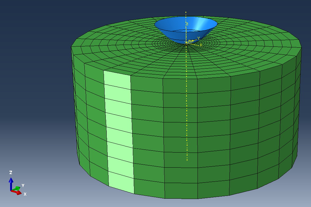
Figure 28 Screenshot of the single crystal indentation model in Abaqus.
Convention for the single crystal mesh
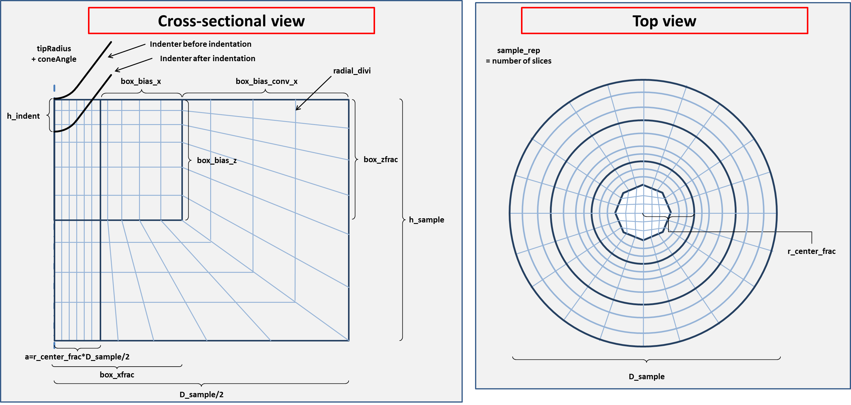
Figure 29 Convention used to define the single crystal mesh.
Bicrystal (BX) indentation
CPFE simulation of indentation close to grain boundaries can provide a good approximation of the local micromechanics in this experiment. While models that take into account the micromechanical effect of the boundary are the subject of ongoing research, most geometrical and kinematic factors are taken into account by employing a local phenomenological crystal plasticity formulation in the simulations.
The function used to run the preCPFE GUI for BX indentation is: A_preCPFE_windows_indentation_setting_BX.m
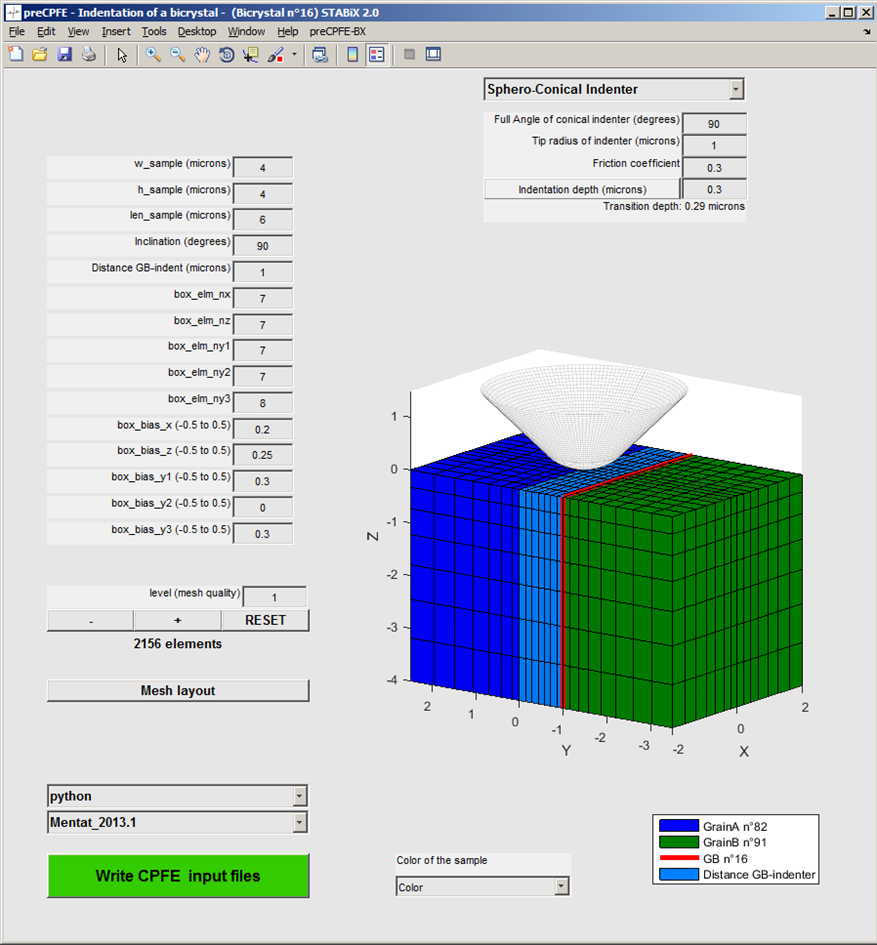
Figure 30 Screenshot of the preCPFE GUI for the bicrystal indentation.
Convention for the bicrystal mesh
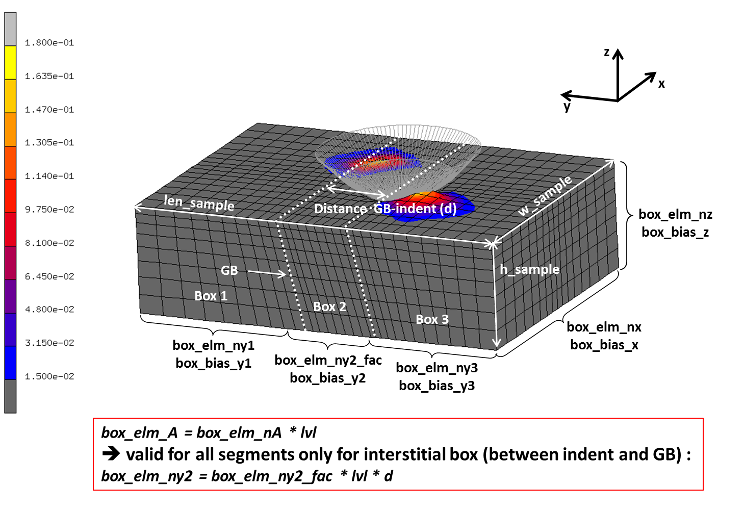
Figure 31 Convention used to define the bicrystal mesh.
Scratch test on SX and BX
CPFE simulation of scratch test in a single crystal or close to a grain boundary is implemented into this GUI. Scratch length and scratch direction have to be set by the user.
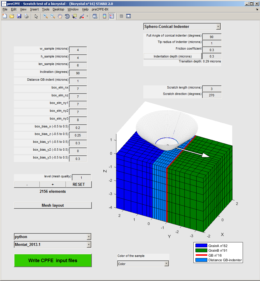
Figure 32 Screenshot of the preCPFE GUI for the scratch test.
Indenter’s geometry
- Currently the following geometries can be used for CPFE simulations:
free topography (from an AFM measurement for instance).
For the Berkovich, Vickers, cube corner indenters and the free topography, the faces and vertices are saved in a structure variable from a patch object. For the cono-spherical and the flat punch, geometries are already implemented in the Python package for MSC.Mentat and Abaqus. It is possible as well to call the Matlab function surf2patch, to return the faces and vertices from a surface object.
Then the function patch2inp is used to generate an Abaqus .inp file, which is used when the CPFE model is created in MSC.Mentat or Abaqus.
It is possible to rotate directly into the GUIs, the Berkovich, Vickers, cube corner indenters and the free topography before the generation of the Abaqus .inp file.

Figure 33 Screenshots of the preCPFE GUI for the bicrystal indentation with Berkovich indenter.
AFM topography
The topography from an Atomic Force Microscopy (AFM) measurement has to be saved into a .txt file in the Gwyddion ASCII format.
The Matlab function used to load and read Gwyddion file is : read_gwyddion_ascii.m
Visit the Gwyddion website for more information.

Figure 35 Screenshot of the preCPFE GUI for the bicrystal indentation with loaded AFM topography of the indenter.
Contact definition
- MSC.Mentat
The indenter is modeled by a rigid body and the sample by a deformable body.
Contact is defined by a bilinear Coulomb friction model.
- Abaqus
The indenter is modeled by a rigid body and the sample by a deformable body.
The external surface of the indenter is defined as the “master” region.
The top surface of the (multilayer) sample is defined as the “slave” region.
If the coefficient friction is different from 0, the classical isotropic Coulomb friction model is used to define the contact between the indenter and the sample.
If the coefficient friction is set to 0, the contact is defined by a frictionless tangential behavior and a hard normal behavior.
A friction coefficient of 0.3 is set by default for every CPFE simulation. It is possible to modify this parameter, by changing its value in the preCPFE GUIs.
Mesh definition
- MSC.Mentat
The mesh is defined by default by hexahedral eightnode elements (hex8).
- Abaqus
The mesh is defined by default by linear hexahedral eightnode elements (C3D8).
It is possible to set quadratic elements (e.g.: C3D20), by changing in the python code the value of the “linear_elements” variable from 1 to 0.
Note
Note that DAMASK incorporates a limited number of different types of element geometries. For a detailed information about the characteristics of each element refer to MSC.Marc and Abaqus user’s manuals.
Python setup
For the generation of the CPFE preprocessing scripts an installation of Python is required together with the Numpy 1.10.4 ans Scipy 0.16.0 packages. Often one of the scientific Python distributions is the easiest way to get up and running (use a Python 2.x distribution). To make sure that STABiX can find the installed Python you will have to either put it on the system’s PATH or put it’s exact location in the user configuration as detailed below.
Adjusting the configuration settings
To write out the necessary files for finite element simulations it is likely that
the user wants to adjust some settings such as the used python installation or the
path where the files are written to.
This can be achieved in the custom menu of the preCPFE GUis: Edit CPFEM config file.
A user specific copy of the default configuration YAML file is created and
opened in the Matlab editor.
To benefit from later changes in the default settings, all
configuration parameters that are not specific to the user’s setup should be deleted
from the user’s CPFE configuration file.
Installing DAMASK
From 2022, DAMASK is not working anymore with Abaqus, but for a usage with older DAMASK and FE softwares (before 2021 at least), follow the next steps.
For instructions on how to set up the DAMASK constitutive simulation code please visit https://damask.mpie.de/index.html.
Writing the CPFE input files
After everything is configured and the model geometry and discretization is optimized, all necessary files to run a CPFE simulation can be generated by pressing the green button. All information will be written to a newly created folder which also includes a timestamp for later reference.
Input files
- MSC.Mentat
a procedure file containing the FEM model (*.proc)
a Python file containing parameters for FEM model (*.mat_FEM_model_parameters.py)
a Python file containing material configuration (*.mat_DAMASK_materialconfig.py)
a MAT-file (binary Matlab format file) storing Matlab workspace variables(*.mat)
a material configuration file (material.config)
an input file for specific indenter’s geometry (*.inp) (optional)
- Abaqus
a Python file containing the FEM model (*.py)
a Python file containing parameters for FEM model (*.mat_FEM_model_parameters.py)
a Python file containing material configuration (*.mat_DAMASK_materialconfig.py)
a MAT-file (binary Matlab format file) storing Matlab workspace variables(*.mat)
a material configuration file (material.config)
an input file for specific indenter’s geometry (*.inp) (optional)
Using the CPFE input files
- MSC.Mentat ‘classic interface’
‘Files’ ==> ‘Current Directory’ ==> Select the folder containing input files
‘Utils’ ==> ‘Procedures’ ==> Select procedure file containing the FEM model (*.proc)
- MSC.Mentat ‘new interface (> 2012)’
‘Files’ ==> ‘Current Directory’ ==> Select the folder containing input files
‘Tools’ ==> ‘Procedures’ ==> Select procedure file containing the FEM model (*.proc)
- Abaqus
‘File’ ==> ‘Set Work Directory…’ ==> Select the folder containing input files
‘File’ ==> ‘Run Script’ ==> Select the Python file containing the FEM model (*.py)
Running a job with DAMASK
Find the full documentation for the use of DAMASK here : https://damask.mpie.de/index.html
- MSC.Mentat
In the JOB RUN menu choose USER SUBROUTINE FILE and select the interface routine DAMASK_marc.f90.
- Abaqus
In the Job Manager > Create… specify the User subroutine file (either DAMASK_abaqus_std.f or DAMASK_abaqus_exp.f).
Note
- For Abaqus, you may have to modify the extension of the subroutine:
.f if the operating environment is Linux;
.for if the operating environment is Windows.
See also
Zambaldi C., “Micromechanical modeling of γ-TiAl based alloys”, PhD Thesis (2010).
Zahedi A. et al., “Indentation in f.c.c. single crystals”, Solid State Phenomena (2012).
Charleux L., “Abapy Documentation”.
Zhao Z. et al., “Temperature dependent constitutive parameters from nanoindentation”, poster for Chems Forum 2019, MSU.